Page 1 of 4
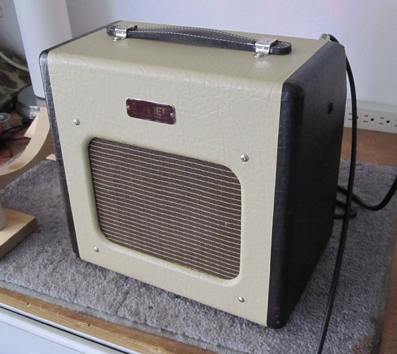
Champion 600 conversion to Champ 5F1
Posted: Tue Dec 13, 2016 4:12 pm
by dubtrub
Re: Champion 600 conversion to 5F1
Posted: Wed Dec 14, 2016 9:53 am
by Mr. Bill
Looks like it will be a cool project. Can't wait to see how it turns out.
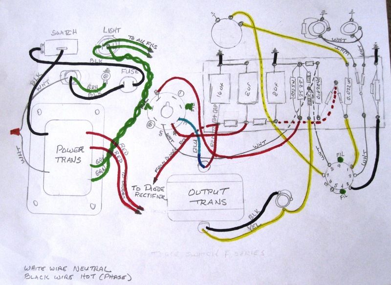
As for your questions, the ac primary wiring that you have drawn up is correct. The hot (black wire) from the ac cord goes to the fuse, then to the power switch and then to the power transformer. The neutral (white wire) goes directly to the other end of the transformer primary winding. Officially, the ground (green wire) should be longer than than either the hot or neutral wire and should be attached to ground at it's own chassis point, that is marked with a ground symbol.
I reviewed the rectifier plan, but I'm not sure that it will work as shown. Does the power transformer high voltage secondary have a center tap that is grounded? If it does, then the series diode string will work, if not then you will have to use a rectifier bridge with it's negative side grounded.
With modern day diodes, you really don't need to have 2 or 3 in series. Fender did that back when the diodes were rated for much lower voltages and putting them in series increased the overall voltage ratings.
Re: Champion 600 conversion to 5F1
Posted: Wed Dec 14, 2016 10:30 am
by dubtrub
Thank you Mr. Bill, I was hoping I could count on you.
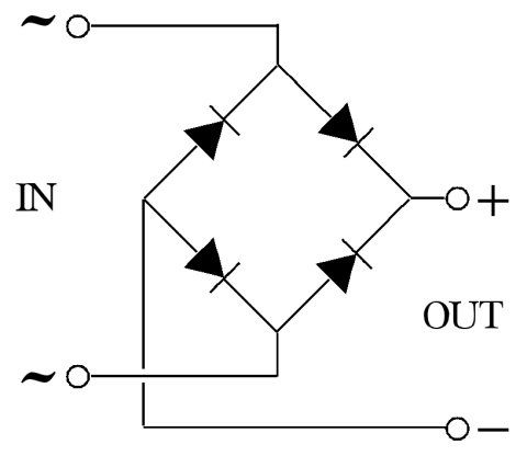
The transformer does not have a center tap. It is rated at 275V. Regarding the bridge rectifier would the following wiring diagram be what you are referring to or is there more to it than something this simple? According to Fender 5F1 schematics it shows 340V at the first high voltage capacitor. I guessing there is more to it.
Re: Champion 600 conversion to 5F1
Posted: Wed Dec 14, 2016 2:24 pm
by Mr. Bill
That's what you need, the negative end is grounded and the positive side is your main B+. The red ac lines from the transformer go to the two sine marked inputs.
Based on the basic rule of thumb, 275 X 1.4 = 385. You should get about 385 vdc as the main B+.
Re: Champion 600 conversion to 5F1
Posted: Wed Dec 14, 2016 3:57 pm
by dubtrub
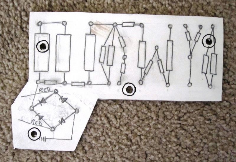
I flipped the above diagram on my pattern drawing maintaining the proper orientation of the diodes to make a cleaner looking circuit board. I will run the ground wire to the board mounting screw designated as the bullseye circle. If this look right I'll go ahead and drill my circuit board for eyelets. BTW, do I need to add a resistor to drop the voltage from 385 down to the 340 as shown on the schematics or is 385v alright?
The diodes are IN4007
Re: Champion 600 conversion to 5F1
Posted: Wed Dec 14, 2016 8:12 pm
by Mr. Bill
That layout for the rectifiers is perfect. The 600 used the same basic system and it worked fine at 366 vdc, so i'd say go for it.
I just looked at the layout for the filaments, you will either need to add two 100 ohm resistors to create a ground reference or ground one side of the filaments and have the other side at 6 vac. If you don't the amp will hum like crazy.
Re: Champion 600 conversion to 5F1
Posted: Wed Dec 14, 2016 8:43 pm
by dubtrub
Mr. Bill wrote:
I just looked at the layout for the filaments, you will either need to add two 100 ohm resistors to create a ground reference or ground one side of the filaments and have the other side at 6 vac. If you don't the amp will hum like crazy.
Will do. I remember you advising me to do that on my 6G6 build as there was no center tap on the transformer. I'm expecting some parts in tomorrow or the next day so I it should go pretty fast once they all arrive.
Re: Champion 600 conversion to 5F1
Posted: Thu Dec 15, 2016 7:51 pm
by dubtrub
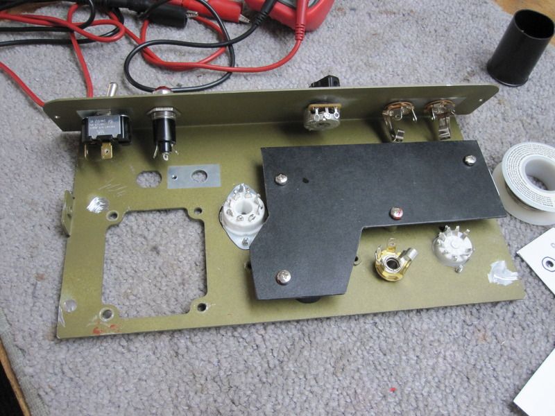
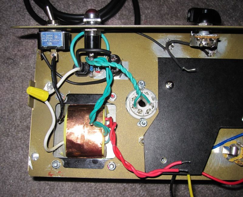
Well, as luck would have it, I didn't get one of the filter caps in today's shipment so that will set me back a few days. I went ahead and installed all the AC components. Those are some tight quarters near the fuse and pilot light. I soldered the 100 ohm resisters to screw terminal before installation making it a lot easier. The heater wires are not soldered in place but look like it in the photo. At this point could it cause any problems firing it up to check the red leads voltage coming off the transformer?
Re: Champion 600 conversion to 5F1
Posted: Fri Dec 16, 2016 5:43 am
by Greg_L
Man, I'm sorry I have no answers for you, but I just wanna say that I'm impressed and a bit jealous of you guys that can build an amp. It's so cool. Best of luck to you with it.
Re: Champion 600 conversion to 5F1
Posted: Fri Dec 16, 2016 10:44 am
by dubtrub
Thanks Greg! I know just enough to get in over my head into then have to ask Mr. Bill to bail me out. But, it is fun!