The modern value is a 0.22uF, the 0.25 is old standard value. There really won't be much difference in performance.
The original tolerance ratings for caps back in the day was typically as high as 20%. The 0.22 value is less than 15% lower than the 0.25 value, so I wouldn't worry about it.
6G6-B Bassman clone project
-
Mr. Bill
- Top Producer
- Posts: 678
- Joined: Tue Aug 19, 2008 12:15 pm
- Location: Chicago, IL
- Contact:
-
dubtrub
- Administrator
- Posts: 3795
- Joined: Sun May 04, 2008 10:12 am
- Contact:
Re: 6G6-B clone project Question
One other thing, on the electrolytic caps, the schematic show (6) 20uf 600v. Looking on the internet I've seen one photo of all replaced with 20-500s. I thought you could go higher voltage but not lower than specs. I hope the 20-500s will work as that is what I ordered because 20-600 were not available. If not, that was an expensive mistake.
Danny Ellison
-
Mr. Bill
- Top Producer
- Posts: 678
- Joined: Tue Aug 19, 2008 12:15 pm
- Location: Chicago, IL
- Contact:
Re: 6G6-B clone project Question
The caps you ordered should be just fine. The schematic shows a B+ voltage of 430 vdc, I'd expect that to be a little higher with modern line voltages, but I doubt that it will reach anywhere near 500 volts.
Again, back in the days when this amp was designed, caps with a 600 volt rating were fairly common. Now, guitar amps are about the only things that would use a cap rated that high and there aren't many of those, so no one makes them anymore.
Again, back in the days when this amp was designed, caps with a 600 volt rating were fairly common. Now, guitar amps are about the only things that would use a cap rated that high and there aren't many of those, so no one makes them anymore.
-
dubtrub
- Administrator
- Posts: 3795
- Joined: Sun May 04, 2008 10:12 am
- Contact:
Re: 6G6-B clone project Question
I've got some IN4700 diodes for the rectifier board. Would one on each coming off of the red taps suffice for the B+ 430v or should I go with two or three on each? The schematic shows three on each side but I read that the new diodes are much more efficient than in 1962 and not as many are required. Man, this is a learning process for me. I sure appreciate the expertise.
Danny Ellison
-
Mr. Bill
- Top Producer
- Posts: 678
- Joined: Tue Aug 19, 2008 12:15 pm
- Location: Chicago, IL
- Contact:
Re: 6G6-B clone project Question
If you mean 1N4007 diodes, one on each side of the high voltage secondary will work just fine. If you want to be bulletproof use two per side.
-
dubtrub
- Administrator
- Posts: 3795
- Joined: Sun May 04, 2008 10:12 am
- Contact:
Re: 6G6-B clone project Question
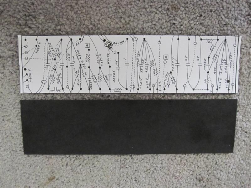
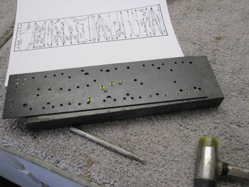
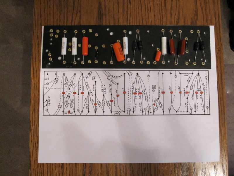
I wasted a good portion of the day trying to free hand draw a pattern for the hole location on the circuit board. After four hours I gave up and tried my luck at reproducing the cropped image of the layout circuit board drawing to the proper size. After wasting too much time on the effort, I sought the help of Mel Waldorf. He saved the day within about two minutes of his computer whiz know how. Now I'm ready to start drilling the holes for the eyelets. I'll simply glue the pattern onto the blank board.
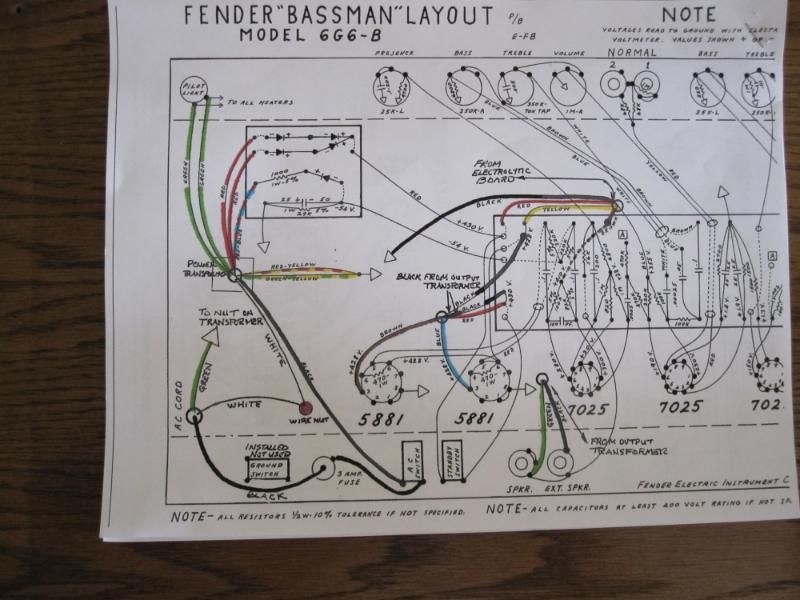
With all the other headaches and confusion going on with this project, I decided to draw the modified version of the 3 prong plug on the layout as well as color code the wires that correspond to the magnetics I have. Naturally all the colored wires on new production plus different manufactures do not match the old layout drawing. While I was at it I redrew the layout on the rectifier board as well as adding some notes to the drawing. I guess this is all part of the fun of learning.
With all the other headaches and confusion going on with this project, I decided to draw the modified version of the 3 prong plug on the layout as well as color code the wires that correspond to the magnetics I have. Naturally all the colored wires on new production plus different manufactures do not match the old layout drawing. While I was at it I redrew the layout on the rectifier board as well as adding some notes to the drawing. I guess this is all part of the fun of learning.
Danny Ellison
-
Mr. Bill
- Top Producer
- Posts: 678
- Joined: Tue Aug 19, 2008 12:15 pm
- Location: Chicago, IL
- Contact:
Re: 6G6-B clone project Question
Good job on the rewire of the ac primary wiring. Technically the ground wire is supposed to go to it's own screw terminal on the chassis and the green wire is supposed to be longer than either the white or the black wires, that way if the cord gets pulled out the ground connection will remain connected.
The one thing that I noticed that you may or may not have already caught is the voltage rating of the bias supply cap. Fender did this wrong for a lot of years. They have applied more than 50 volts on the 50 volt bias cap. Even though they did this these caps rarely failed. A modern cap may not hold up as well. I'd suggest at least a 63 volt cap there.
Great idea for working out the layout of the fiberboard. If you haven't already started drilling, you might want to wait to see how the components that you have are going to fit the layout. To me it looks like the width of the layout should shrink a little to keep the components away from the edges of the board.
-
dubtrub
- Administrator
- Posts: 3795
- Joined: Sun May 04, 2008 10:12 am
- Contact:
Re: 6G6-B clone project Question
Thanks for the caution on the cap. Just to make certain, are you referring to the 25-50 capacitor on the rectifier board as the bias supply cap? I don't have all this electronic terminology figured out yet.  I have 100uf-100v in my spare parts box would that be alright?
Danny Ellison
-
Mr. Bill
- Top Producer
- Posts: 678
- Joined: Tue Aug 19, 2008 12:15 pm
- Location: Chicago, IL
- Contact:
Re: 6G6-B clone project Question
Yes, that's the one, a 100 volt rating will be fine there.
Sorry for the tech terms, just ask if I mention anything that you're unsure of. The bias supply is used to set the idle point for the two output tubes. Just like a car engine needs to idle fast enough not to stall, but not so fast as to waste energy and overheat, the output tubes need to be turned on enough to amplify the signal cleanly but not so much that they overheat.
One important point regarding the bias supply is that it is a negative voltage. Be sure to install the diode and the cap with the correct polarity. Well, that point really applies to all of the polarized components in the entire amp.
-
dubtrub
- Administrator
- Posts: 3795
- Joined: Sun May 04, 2008 10:12 am
- Contact:
Re: 6G6-B clone project Question
Today I drilled and installed the eyelets on the circuit board. After setting the eyelets, I began populating the board by 'hanging' all the capacitors. Nothing gets soldered until I've hung all of the components. Main thing for me is to check once, twice, three times and then when I'm certain, I'll check a couple more time to be sure that I got the right caps and resistors in the right place. The caps are the easy part but the resistors have to be checked and rechecked for the right value before hanging them. I've been known to have a little difficulty reading all the bands on a resistor properly.
Danny Ellison
Return to “Amp Tech Q&A and Repair Shop”
Who is online
Users browsing this forum: No registered users and 100 guests